This post explains the concept of 'flattening sub-circuits' used in digital circuit simulation tools like «Boolflow». It clarifies how complex blocks are broken down into their fundamental components to make the simulation process more efficient and manageable.
Today, we delve into an interesting topic from the world of digital circuit design and simulation, inspired by news about the browser-based logic simulator «Boolflow» and its technique for 'flattening sub-circuits'. Imagine you're building a vast city using LEGO blocks. Instead of constructing every single house or building from scratch, you might use pre-built designs for small homes or shops (these are your 'sub-circuits' or 'blocks'). You can then reuse these designs multiple times throughout your city.
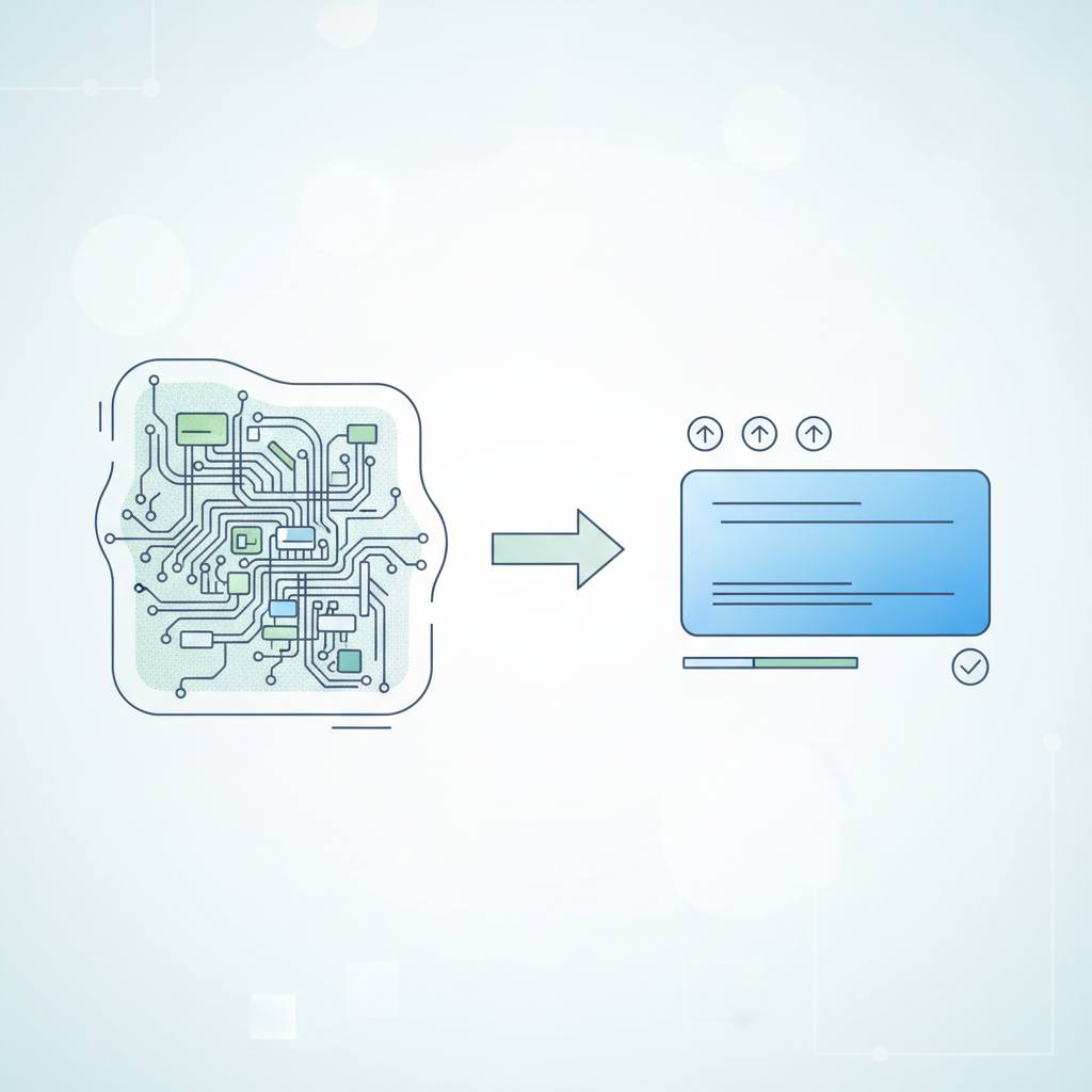
When you want to understand how your entire city functions – for example, how traffic flows or how services connect – it would be challenging to analyze each pre-built design as a single, complex block. This is where the concept of 'flattening' comes into play. Flattening simply means breaking down these pre-built designs or 'sub-circuits' into their individual, smaller, basic parts. So, instead of seeing a 'small house', the simulator (or planner) sees each individual brick and every wire connecting them.
In the realm of digital circuits, 'sub-circuits' are complex logic blocks like a Full Adder or a Register, which are themselves composed of simpler logic gates (AND, OR, NOT). When a simulation program like «Boolflow» prepares a circuit, it 'flattens' it. This means it takes each complex block and replaces it with its internal details of basic logic gates and wires. The result is one massive 'flat' circuit, consisting only of the simplest components that the simulator can understand and process easily and efficiently.
To keep track of every single part, even when sub-circuits are nested (a block inside another block) or when the same sub-circuit is used multiple times, 'Path IDs' are employed. Imagine you name the floors in the first house 'house_1/first_floor' and in the second house 'house_2/first_floor'. This ensures that every element within the flattened circuit has a unique name, making it easier for the simulator to track its state and behavior. This approach allows engineers to design complex circuits systematically using reusable components, while the simulator remains capable of understanding and analyzing the circuit at a lower, more detailed level. This significantly simplifies the simulation process and makes it much more effective.